How to Choose Solar Power for Outdoor Security Cameras
Choose a solar power system for outdoor security cameras by comparing load, winter solar access, battery autonomy, site protection and lifetime cost.
By Maxsol Team

The right solar power system for outdoor security cameras must support the complete site load—not just the camera—through low-sun periods while matching its electrical interfaces, installation environment and maintenance plan. Start with measured or manufacturer-specified power consumption, then check winter solar access, required autonomy, output compatibility and room for expansion.
Do not select a system from panel watts or nominal battery watt-hours alone. A dependable off-grid design treats the camera, infrared illumination, wireless link, network equipment, conversion losses and standby loads as one continuous system. For New Zealand sites, seasonal sun angles, vegetation, hills, wind exposure, coastal conditions and temperature variation can all affect the final choice.
1. Match the camera load and electrical interfaces
Build a load schedule before comparing solar systems. Record every device that will operate from the system, its supply voltage, typical demand, maximum demand and operating hours.
A site may include:
- One or more fixed, PTZ or multi-sensor cameras
- Infrared or white-light illuminators
- A 4G/5G router or wireless CPE bridge
- A PoE injector or PoE switch
- DC-DC converters
- Edge storage or another recording device
- Cabinet fans, heaters or environmental controls
- Monitoring and communications equipment
Use the equipment manufacturer’s maximum or worst-case consumption where possible. Average figures can understate demand when infrared LEDs switch on, a PTZ mechanism moves, a radio transmits at higher power or a heater operates.
Confirm voltage and connector compatibility
A camera described as “12V” is not automatically compatible with every 12V solar output. Check:
- Permitted input-voltage range
- Maximum current
- Connector type and polarity
- Voltage drop over the cable run
- Surge and transient protection requirements
- Whether the camera requires DC power or PoE
- Whether outputs are individually protected
- The combined current limit across all outputs
This distinction is particularly important for IP cameras. A solar system with DC12V outputs does not directly provide standard PoE unless compatible conversion or injection equipment is added. Include that equipment’s own power demand and conversion losses in the load schedule.
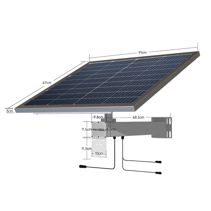
For example, the Maxsol CS8040 80W, 45Ah solar system documents an 80W monocrystalline panel, a 12.8V 45Ah 576Wh LiFePO4 battery, MPPT control and three DC12V outputs. These specifications make it a useful selection reference, but they do not establish compatibility with a particular camera, PoE injector or network device.
Size for the whole 24-hour load
As a hypothetical assumption, consider a site with an 8W camera, a 5W wireless bridge and 2W allowed for supporting electronics and conversion losses. The design load would be based on approximately 15W continuously, not the camera’s 8W rating alone. This example is only a sizing illustration; it is not measured product performance or a runtime claim.
Cable length also matters. A long low-voltage DC run can cause substantial voltage drop, especially at higher currents. It may be better to position the power system close to the load, raise the distribution voltage and convert locally, or use an appropriately designed PoE arrangement. Any such approach must remain within the input limits of every connected device.
For the full energy calculation process, including daily watt-hours and system losses, use this guide to sizing an off-grid solar power system for CCTV rather than choosing from a nominal panel or battery figure.
2. Assess seasonal solar access and shading
A solar camera installation should be designed around the difficult part of the year, not a clear summer day. In New Zealand, winter sun is lower in the sky and daylight hours are shorter. Local topography, tree lines, structures and rapidly changing weather can further reduce useful solar exposure.
Inspect the proposed site at the panel location and consider:
- The sun path across different seasons
- Early-morning and late-afternoon obstructions
- Hills, buildings, poles and signs
- Existing and future vegetation growth
- Partial shading across the panel
- Dirt, salt deposits, bird fouling or leaf accumulation
- Whether the mounting angle allows practical cleaning
- Wind exposure and the suitability of the mounting structure
A panel may appear unshaded at midday but lose a significant part of its charging window in the morning or afternoon. Partial shading can also affect output more severely than a simple percentage estimate suggests, depending on panel construction and system behaviour.
Use site evidence rather than a regional assumption
Online solar estimates can help with early planning, but they do not replace a site survey. Two installations in the same district can have very different results if one has a clear northern aspect and the other sits below a ridge or among trees.
For a security project, document the panel position with photographs and note the survey date and time. Where winter performance is critical, model or inspect the winter sun path rather than assuming summer observations apply year-round.
The panel should generally face the direction that provides the best usable solar window for the site, but orientation cannot be separated from shading, wind loading, mounting access and tamper risk. A theoretically ideal angle may be impractical if it exposes the panel to damage or makes maintenance unsafe.
Compare panel capacity only after assessing the site
A larger panel can provide more charging opportunity, but panel wattage alone does not solve persistent shade. It must also stay within the controller’s supported PV voltage, current and power limits.
The Maxsol CS12060 120W, 60Ah solar system documents a 120W monocrystalline panel, 12.8V 60Ah 768Wh LiFePO4 battery, MPPT controller and three DC12V outputs. When evaluating it—or any packaged system—confirm the current datasheet and supplied configuration rather than assuming a panel or controller can be substituted freely.
If the proposed location cannot provide reliable solar exposure, consider relocating the panel while keeping the camera in the required position. Account for the resulting cable distance, voltage drop, lightning exposure, physical protection and installation cost.
3. Set autonomy and battery requirements
Autonomy is the period the system must support the load when solar input is insufficient. The appropriate target depends on site criticality, expected weather patterns, access for maintenance and the operational consequence of losing surveillance.
A low-risk temporary site may accept a different design margin from a remote gate, critical infrastructure location or communications relay. Procurement documents should therefore state the required service objective rather than simply asking for “a solar CCTV kit”.
Specify:
- Whether recording must continue continuously
- The acceptable response to prolonged poor weather
- Whether non-critical loads can be shed
- Whether remote low-voltage alerts are required
- The minimum battery state at which equipment should disconnect
- How quickly the system should recover after a low-energy event
- Whether technicians can reach the site promptly
Nominal battery capacity is not delivered energy
Battery watt-hours are useful for comparing products, but nominal capacity is not the same as usable energy at the connected load. Available energy is affected by controller settings, permitted depth of discharge, temperature, battery protection, conversion losses, cable losses, load variation and battery condition.
For this reason, a 576Wh, 768Wh or 1920Wh battery rating must not be treated as a guaranteed runtime figure. There is no universal autonomy or 24/7 performance guarantee based on nominal watt-hours alone.
LiFePO4 batteries are commonly considered for solar surveillance because of their characteristics as an energy-storage technology, but they still require correct charging, temperature management and protection. The separate guide to LiFePO4 battery considerations for solar CCTV explains these issues without repeating the full storage analysis here.
Always verify permitted charging temperatures and the protection functions in the current battery and controller documentation. A battery may be able to discharge under conditions in which charging is restricted. This matters for exposed inland, elevated or frost-prone locations.
Plan for graceful degradation
Where a project cannot justify enough storage for every conceivable weather event, define what happens when energy becomes limited. Possible strategies include:
- Keeping the primary camera active while disconnecting auxiliary lighting
- Reducing radio transmission frequency where the system supports it
- Using event-based functions instead of continuous high-power operation
- Sending an alert before low-voltage disconnection
- Providing a safe shutdown and automatic recovery procedure
These are system-design options, not assumed functions of the linked products. Confirm support in the camera, controller, communications and power equipment before relying on them.
4. Check installation protection and maintenance needs
Outdoor reliability depends on more than the panel and battery. The mounting system, enclosure, cable entries, earthing strategy, connectors and maintenance access all affect whether the installation remains serviceable.
Before purchase, confirm the specified protection for:
- Rain and wind-driven water
- Dust and insects
- UV exposure
- Corrosion, particularly near the coast
- Operating and storage temperatures
- Condensation
- Cable strain and abrasion
- Surge and lightning exposure
- Vandalism and unauthorised access
Do not assume that every component within an outdoor solar package has the same environmental rating. Ask for the rating and permitted installation orientation of the enclosure, connectors, controller and any external conversion equipment.
Design the physical layout as one system
A practical site plan should show:
- Panel and mounting position
- Battery and controller location
- Camera and radio locations
- Cable routes and distances
- Isolation and protection points
- Earthing or bonding provisions where required by the design
- Technician access for inspection and replacement
Avoid cable entries that can collect water or direct runoff towards seals. Allow drip loops where appropriate and use connectors suited to the intended environment. Dissimilar metals, exposed fasteners and untreated mounting hardware can become maintenance problems in corrosive locations.
Wind exposure deserves particular attention in open rural, hilltop and coastal installations. Panel area creates structural loading, so mounting hardware and the supporting pole or structure must be assessed for the actual site. Product wattage does not indicate whether a mounting arrangement is structurally suitable.
Make routine maintenance possible
Even a correctly sized system needs inspection. A maintenance plan may include:
- Cleaning the panel when contamination affects charging
- Removing vegetation that creates new shade
- Checking mounts and fasteners
- Inspecting cable glands and seals
- Looking for corrosion, insect ingress and cable damage
- Reviewing battery and controller status
- Testing camera, network and alert functions
- Confirming that new equipment has not increased the load
Remote data can reduce unnecessary visits, but only if the system exposes useful information and that data can be carried over the site network. RS485 is documented as optional for the CS8040 and CS12060. Confirm the supplied configuration, protocol details and compatibility with the intended monitoring platform; the presence of an interface does not by itself provide end-to-end remote management.
5. Compare lifecycle cost, integration and expansion
The lowest initial equipment cost is not necessarily the lowest project cost. Compare systems over the planned service period, including design work, installation, mounting, conversion equipment, site visits, replacement access and future expansion.
The first commercial decision is often whether to use a packaged solar power system or specify the panel, controller, battery, enclosure and outputs separately.
| Selection issue | Packaged solar power system | Separately specified components |
|---|---|---|
| Design effort | Can reduce component-selection work, but load and site validation are still required | Requires detailed electrical, mechanical and environmental engineering |
| Interface risk | Lower only when documented outputs match the load | Greater integration responsibility, but more interface flexibility |
| Expansion | Limited by the controller, battery, panel and available outputs | Can be designed around planned cameras, radios or auxiliary loads |
| Procurement | Fewer major line items to compare | More components, suppliers and compatibility checks |
| Servicing | May simplify like-for-like replacement if parts remain identifiable | Individual components may be easier to replace or upgrade |
| Documentation | Supplied configuration must be checked carefully | Installer must maintain a complete system-level record |
| Best fit | Repeatable installations with clearly bounded loads | Unusual loads, long cable runs or project-specific control requirements |
A packaged system is not automatically plug-and-play. The buyer still needs to verify connectors, output limits, controller settings, cable sizes, environmental protection and compatibility with the camera network.
Separately specified components offer more control but create additional integration responsibility. The designer must confirm that the panel matches the controller, the controller matches the battery chemistry and limits, the battery supports the expected load, and all protection devices are correctly selected.
Compare documented configurations, not wattage alone
The three Maxsol systems below illustrate different documented panel, battery and DC-output configurations. They are selection examples, not tested compatible bundles for any particular camera installation.
| Example system | Documented solar configuration | Documented nominal battery | Documented outputs | Selection point |
|---|---|---|---|---|
| CS8040 | 80W monocrystalline panel | 12.8V 45Ah, 576Wh LiFePO4 | Three DC12V outputs | Compare against smaller load schedules and available solar access |
| CS12060 | 120W monocrystalline panel | 12.8V 60Ah, 768Wh LiFePO4 | Three DC12V outputs | Offers a different panel and storage level for comparison |
| CS400150 400W, 150Ah solar system | Two 200W modules, 400W total | 12.8V 150Ah, 1920Wh LiFePO4 | Four DC12V outputs | Compare for higher aggregate loads or greater design margin |
All three document MPPT control. Before specifying any of them, verify the current datasheet and supplied configuration for controller PV voltage, current and power limits, as well as battery charging temperatures and protection. Do not assume that battery capacity scales directly into usable runtime.
Allow for future site changes
Expansion may involve more than adding another camera. A site could later require a higher-power radio, additional illumination, analytics equipment, a second network path or environmental controls.
Ask whether the proposed system has enough:
- Continuous output capacity
- Peak current capability
- Physical DC outputs or network ports
- Controller headroom
- Panel input capacity
- Battery storage margin
- Enclosure space
- Cable capacity
- Monitoring capability
Unused capacity has a cost, but a system designed with no practical margin may require substantial rework when the site changes. Record both the current load and the approved future load so procurement teams can compare proposals consistently.
Supplier selection checklist
A credible proposal should make its assumptions visible. Before approving a solar power system for outdoor security cameras, request or confirm the following:
- Complete load schedule: Every camera, radio, converter, illuminator and supporting device is included.
- Maximum and continuous demand: The design does not rely solely on a camera’s typical power figure.
- Electrical compatibility: Output voltage, current, polarity and connector types match the connected equipment.
- PoE strategy: Any injectors, switches or converters are identified and included in the energy budget.
- Site solar assessment: Seasonal shading, panel position and obstructions are documented.
- Autonomy objective: The required low-sun operating period and acceptable failure response are stated.
- Battery assumptions: Nominal capacity is distinguished from expected usable energy.
- Controller limits: PV voltage, current and power boundaries are confirmed from current documentation.
- Temperature limits: Battery charging and equipment operating conditions suit the intended site.
- Environmental protection: Enclosure, connectors, cable entries and mounting hardware are specified for the location.
- Cable calculations: Distance, conductor size, current and voltage drop have been checked.
- Protection design: Isolation, overcurrent protection, surge measures and any project-required earthing are defined.
- Mounting responsibility: The proposal identifies who assesses the pole, structure and wind exposure.
- Monitoring requirements: Local indicators, alarms and optional interfaces are clearly distinguished.
- Maintenance access: Panel cleaning, vegetation control, inspection and component replacement are practical.
- Expansion allowance: Future load, output and enclosure requirements are documented.
- Configuration control: Model numbers, options and supplied components appear on the quotation and final records.
- Commercial terms: Warranty scope, exclusions, replacement process and technical support are confirmed directly with the supplier.
The practical next step is to compare the linked Maxsol models against the project’s output or port count, total load, cable and network distance, power interfaces, environmental conditions and management requirements. Validate the selected configuration against current documentation before treating it as compatible with the cameras or the wider surveillance network.