Off-Grid Solar Design Mistakes: Fault Isolation Guide
Trace dawn shutdowns, PoE reboots, poor recharge and winter outages with practical checks for New Zealand off-grid solar sites.
By Maxsol Team

The most common off grid solar power system design mistakes become visible as repeatable faults: equipment shuts down before sunrise, PoE devices reboot, the battery never fully recharges, or the site fails only in winter or hot weather. The fastest way to isolate these problems is to measure each energy and interface stage rather than simply adding a larger panel or battery.
Start with the fault time, battery voltage trend, actual load and charging behaviour. Then determine whether the shortfall comes from energy demand, solar recovery, component compatibility, environmental conditions or inaccessible maintenance.
Fault-isolation table for common off-grid solar failures
All scenarios below are hypothetical. They illustrate diagnostic methods rather than measured performance or a diagnosis of any installation.
| Symptom | Likely design cause | What to measure or confirm | Corrective direction |
|---|---|---|---|
| Site shuts down shortly before dawn | Night-time energy demand exceeds usable stored energy; battery low-voltage protection operates; daytime charging was incomplete | Battery voltage and, where available, state-of-charge trend from sunset to shutdown; overnight Wh; controller low-voltage settings; battery temperature | Recalculate usable overnight energy, reduce loads, correct protection settings where permitted, or increase battery and recharge capacity together |
| Camera, radio or PoE switch repeatedly reboots | Startup surge, IR activation, voltage drop, converter overload or incompatible PoE output | DC voltage at the powered device during reboot; peak current; cable voltage drop; PoE voltage, polarity, pinout and protocol; converter temperature | Correct the PoE interface, shorten or resize DC conductors, provide suitable surge margin, or select a correctly rated converter |
| Battery fails to recharge after a normal day | Array energy is insufficient, shading is present, MPPT limits are exceeded, or daytime loads consume most generated energy | PV voltage and current; daily charging Wh; load Wh during daylight; shading by time of day; controller charge stage and limits | Remove avoidable shading, reduce demand, or resize the array and controller using the design month rather than annual averages |
| Site works in summer but fails in winter | Design used annual-average sunshine, did not allow for consecutive poor-solar days, or has an unsuitable panel angle or shaded winter solar window | Site-specific design-month solar resource; daily load; winter shading; daily battery recovery; autonomy assumptions | Recalculate around the least favourable operating period and verify that the array can both run the load and replace overnight consumption |
| Failures appear on hot, sunny days | Enclosure heat increases conversion losses or triggers thermal protection; charging conditions exceed component limits | Internal enclosure temperature at the battery, controller and converter; load current; ventilation; direct sun exposure; manufacturer temperature limits | Reduce solar heat gain, improve passive thermal design, relocate heat-producing components or derate equipment according to its documentation |
| System operates after service but deteriorates again | Connectors, panels, vents or batteries cannot be inspected safely and consistently | Access to terminals, fuses, isolation points, panel surfaces, logs and replaceable components | Redesign access and labelling so routine inspection does not require dismantling unrelated equipment |
One symptom can have several causes. A dawn shutdown, for example, may reflect a small battery, but it may also result from a shaded array that never restored the energy used the previous night. Treat the complete energy path as one system.
Mistaking nominal power and energy for usable supply
Watts and watt-hours answer different questions:
- Watts (W) describe the instantaneous rate of power use or production.
- Watt-hours (Wh) describe energy accumulated over time.
- Amp-hours (Ah) are meaningful only when the battery voltage is also stated.
A 20W load operating continuously requires more than a supply capable of producing 20W. It also requires enough daily energy:
Daily load energy = load power × operating hours
Hypothetical assumption: an 18W continuous load uses 432Wh per day before allowing for converter loss, cable loss, startup events, temperature effects or battery protection limits.
Nominal battery energy is calculated from voltage and capacity:
Nominal battery energy in Wh = nominal voltage × Ah
This is why comparing batteries only by Ah is misleading. A 45Ah battery at one voltage does not store the same nominal energy as a 45Ah battery at another voltage. Even after converting to Wh, nominal battery energy is not the same as usable energy delivered to the load. Battery protection thresholds, permitted depth of discharge, temperature and conversion losses all reduce what reaches the equipment.
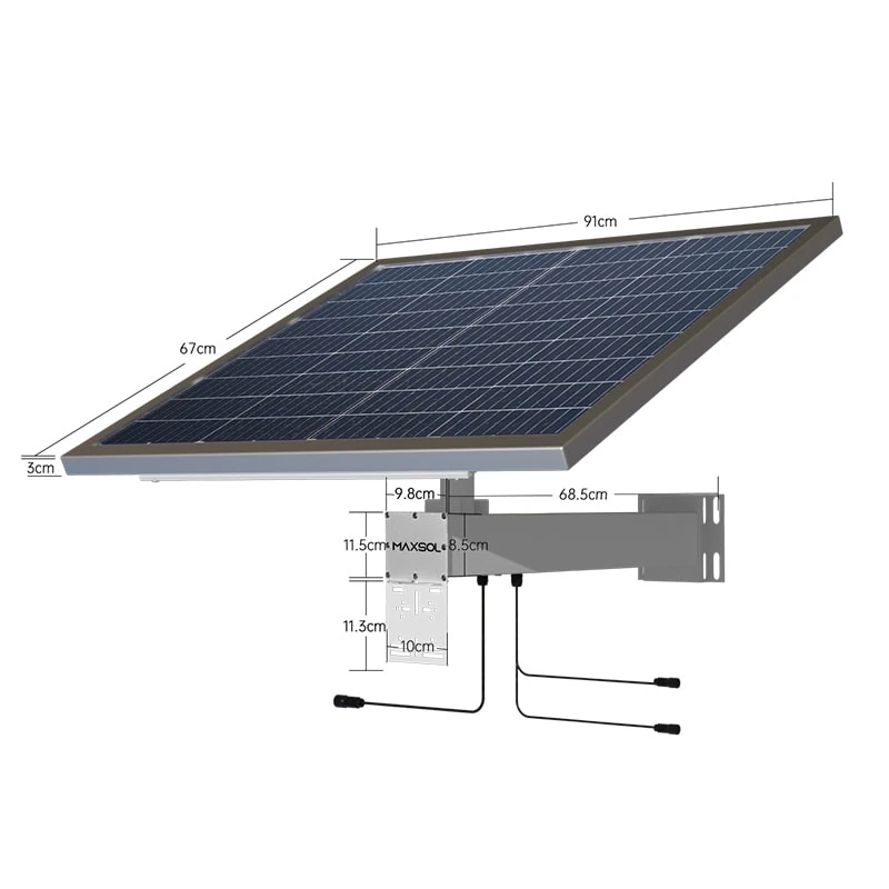
For example, the Maxsol CS8040 80W and 576Wh solar system documents an 80W monocrystalline panel, a 12.8V 45Ah 576Wh LiFePO4 battery, an MPPT controller and three DC12V outputs. These are nominal component specifications, not a promise of usable autonomy or continuous operation for a particular load.
The Maxsol CS12060 120W and 768Wh solar system documents a 120W monocrystalline panel, a 12.8V 60Ah 768Wh LiFePO4 battery, an MPPT controller and three DC12V outputs. Its larger nominal panel and battery figures do not by themselves establish runtime, winter recovery or compatibility with a given installation.
For either example, calculate the site load first, then apply the battery manufacturer’s permitted discharge limits and the losses of every device in the power path. The two systems are selection references, not a tested compatible bundle with cameras, switches, radios or converters.
For the underlying calculation process, use this guide to size an off-grid solar power system for CCTV.
Sizing for average sunshine instead of the design month
Annual-average solar resource can make a design look balanced while hiding the period in which it is most likely to fail. A New Zealand site expected to operate throughout the year should be checked against its relevant design month and actual horizon, not just an annual average or an ideal unshaded estimate.
A valid recharge calculation needs to answer two separate questions:
- Can the array support loads operating during solar hours?
- Can it also replace the energy removed from the battery overnight and during previous low-solar periods?
A larger battery cannot correct an array that has a persistent energy deficit. It may only delay the shutdown. Similarly, increasing panel capacity without confirming MPPT limits can create a new compatibility problem.
Use site-specific inputs for:
- the required operating season;
- panel orientation and tilt;
- the visible solar horizon;
- morning and afternoon shading;
- expected soiling or obstruction;
- the number of low-generation days the system must tolerate;
- the energy needed to restore the battery after those days.
Do not assume all daylight hours are equivalent to full rated panel output. Panel nameplate power is measured under defined conditions and is not the same as daily harvested energy.
A practical diagnostic is to compare daily load Wh with daily charging Wh over representative conditions. If charging appears substantial but the battery state declines each day, the system has a continuing energy deficit, inaccurate monitoring or a charging problem. Changing battery capacity alone does not remove that deficit.
Omitting night loads, conversion loss and startup demand
Security and networking equipment rarely maintains one fixed power level. A camera may draw more when infrared illumination activates. A wireless radio may vary with traffic or link conditions. A heater, fan or illuminator may operate only at particular temperatures or times. A PoE switch or converter also consumes power while delivering power to another device.
Create a load schedule that separates:
- daytime and night-time demand;
- base, typical and credible peak power;
- IR illuminators and auxiliary lighting;
- radios, access points and wireless bridges;
- PoE switch or injector consumption;
- DC conversion losses;
- enclosure fans, heaters and controls;
- startup and simultaneous restart demand.
Hypothetical assumption: suppose a camera uses 8W by day and 13W for 12 hours at night when IR is active, while a radio uses 7W continuously. The daily load is:
- Camera:
(8W × 12h) + (13W × 12h) = 252Wh - Radio:
7W × 24h = 168Wh - Combined device load:
420Wh per day
That 420Wh excludes cable loss, conversion loss and any other equipment. It must not be compared directly with nominal battery Wh as if all stored energy were deliverable.
Repeated PoE reboots deserve waveform or logged measurements where possible. A handheld voltage reading taken after the reboot may miss the brief sag that caused it. Measure voltage at both the battery-side converter input and the remote powered device while IR, radios and other loads start.
Where LiFePO4 is being considered, review its operating characteristics and protection requirements rather than treating the chemistry label as a complete design specification. This overview of LiFePO4 battery considerations for solar CCTV explains the underlying battery selection factors. Always confirm the current battery documentation, including charging temperature limits and protection behaviour.
Mismatching battery, MPPT and PoE interfaces
Components can have adequate headline power ratings and still be electrically incompatible. Verify each interface as a range and protocol, not merely as a nominal voltage.
Battery-to-controller checks
Confirm:
- supported battery chemistry and nominal voltage;
- charge-voltage settings;
- maximum charge and discharge current;
- low-voltage disconnect and reconnect behaviour;
- battery-management-system protection behaviour;
- permitted charging temperatures;
- conductor, fuse and isolation ratings.
Incorrect charge settings can leave a battery chronically undercharged or cause protection to interrupt charging. Do not change limits without the applicable manufacturer documentation.
Panel-to-MPPT checks
Confirm the current datasheet and supplied controller configuration for:
- maximum PV open-circuit voltage;
- MPPT operating-voltage range;
- maximum PV input current;
- maximum accepted PV power;
- panel open-circuit voltage under expected low temperatures;
- connector type, polarity and array configuration.
A panel’s nominal wattage does not prove controller compatibility. Cold conditions can raise panel open-circuit voltage, while heat can reduce operating voltage. Both ends of the expected range matter.
DC-to-PoE checks
“PoE” does not identify one universal electrical interface. Verify the required voltage, polarity, pinout, output power and whether the powered device expects standards-based negotiation or a particular passive arrangement.
The Maxsol POE24V adjustable DC-to-PoE converter documents a 12–36V DC input, an adjustable 12–57V PoE output, Gigabit Ethernet and an LCD voltage display. Its documented continuous load for 12V-to-48V conversion is no more than 30W. The stated efficiency of up to 94% is a maximum, not a guaranteed value to use in an energy budget.
The available facts do not establish IEEE powered-device detection or negotiation. Before connecting equipment, confirm:
- required output voltage;
- positive and negative pin assignment;
- passive or negotiated PoE requirements;
- peak and continuous power;
- cable length and voltage drop;
- startup behaviour;
- whether the powered device accepts the selected output.
Do not use adjustable output as a substitute for interface verification. An incorrect setting or pinout can prevent operation or damage equipment.
Ignoring shading, temperature and maintenance access
Electrical calculations assume the equipment can operate in its real environment. Shading, enclosure temperature and service access can each turn an apparently adequate design into an unreliable site.
Shading must be checked by time and season
A brief obstruction during a high-value charging period may matter more than light shading at another time. Inspect the solar path for vegetation, poles, antenna structures, terrain, fencing and nearby equipment. Consider how the path changes through the required operating season.
When investigating poor recharge, compare PV voltage and current at different times rather than relying on one midday reading. Partial shading can be intermittent, and future vegetation growth should be considered in the mounting location.
Measure temperature inside the enclosure
Ambient temperature does not show what the controller, battery and converter experience in a closed cabinet exposed to sun. Measure near the components, preferably during the operating condition associated with the fault.
Check whether:
- direct sun heats the enclosure;
- electronics are mounted too closely together;
- cable entries restrict intended ventilation;
- a converter is operating near its continuous limit;
- battery charging is attempted outside the documented temperature range;
- thermal protection coincides with the outage.
Ventilation changes must not compromise the enclosure’s required environmental protection. Use component temperature limits and appropriate derating information from current datasheets.
Design for safe inspection
A technically adequate system can still fail repeatedly if technicians cannot reach measurement points or isolate components safely. Provide practical access to:
- battery and PV terminals;
- fuses and disconnects;
- controller indicators or logs;
- converter settings;
- cable labels and polarity markings;
- panel surfaces and mounting hardware;
- communication ports, including optional monitoring interfaces where supplied.
Both referenced Maxsol solar systems document optional RS485. Confirm whether it is included in the supplied configuration and what monitoring functions are supported rather than assuming remote diagnostics are available.
Validate the corrected design with a commissioning checklist
Commissioning should prove the corrected system across load, charging and fault conditions. Recording baseline measurements also makes later troubleshooting faster.
Energy and load
- Record every continuous, scheduled and intermittent load.
- Measure day and night power rather than relying only on labels.
- Trigger IR illumination, radios, heaters, fans and other conditional loads.
- Record simultaneous startup and credible peak demand.
- Convert the complete load schedule to daily Wh.
- Include conservative conversion and cable-loss allowances.
- Distinguish nominal battery Wh from permitted usable energy.
Solar recovery
- Confirm the design-month solar input for the actual site.
- Inspect the solar horizon and record shading by time.
- Verify panel orientation, mounting and connector polarity.
- Check PV open-circuit voltage against the controller’s maximum.
- Check operating voltage, current and power against all MPPT limits.
- Demonstrate that daytime generation supports the live load and battery recovery.
- Record whether the battery reaches the intended charge state after overnight use.
Battery and protection
- Confirm chemistry, nominal voltage and controller charge profile.
- Verify low-voltage disconnect and reconnect settings.
- Check fuse, conductor and isolation-device ratings.
- Confirm documented charging and discharging temperature limits.
- Test how the system recovers after a protection event.
- Verify monitoring values against direct measurements where practical.
PoE and networking
- Confirm PoE voltage, polarity, pinout and protocol at each powered device.
- Verify continuous and peak power against the converter rating.
- Measure voltage at the remote device under full load.
- Check Ethernet link speed and stability.
- Test cable distance under night-time and startup loads.
- Confirm that a system restart does not create a simultaneous overload.
Environment and serviceability
- Measure enclosure temperature near each critical component.
- Check cable glands, drainage, ventilation and direct solar exposure.
- Confirm that panels, terminals, fuses and settings remain accessible.
- Label conductors, protection devices and adjustable outputs.
- Save commissioning readings, settings and configuration details.
- Recheck performance during the site’s relevant low-solar conditions.
No single commissioning reading proves year-round autonomy. A corrected design should show a balanced daily energy budget, adequate recovery margin, compatible interfaces and stable operation under realistic peak loads.
As a practical next step, compare the linked Maxsol system and converter examples with your required port count, load profile, cable distance, power budget, environmental conditions and management needs. Verify current datasheets and the supplied configuration before treating any components as a compatible system.