MPPT vs PWM for Outdoor Solar Power in New Zealand
Compare MPPT and PWM solar charge controllers for outdoor systems, including voltage matching, winter performance, LiFePO4 checks and total cost.
By Maxsol Team

For most year-round outdoor power systems, MPPT is the stronger choice because it can convert surplus panel voltage into useful charging current and accommodate a wider range of array configurations. These advantages matter when powering surveillance, wireless networking or other continuous loads through changing New Zealand seasons.
PWM can still be appropriate for a small, tightly voltage-matched system where initial cost and simplicity matter more than energy harvest. However, controller type alone does not determine performance. The panel’s cold-weather open-circuit voltage, available current, battery charging profile, controller limits, cabling and standby consumption all need to work together.
How MPPT and PWM charge controllers operate
Both controller types regulate energy flowing from a solar panel to a battery. The difference is how they use the panel’s available voltage.
PWM connects the panel close to battery voltage
A pulse-width modulation controller rapidly switches the connection between the panel and battery. When charging, it generally pulls the panel’s operating voltage towards the battery voltage.
This approach is relatively simple, but it means a panel capable of producing its maximum power at a substantially higher voltage may not operate at that maximum-power point. The unused voltage is not automatically converted into extra charging current.
PWM therefore works best when:
- The panel’s electrical characteristics suit the nominal battery voltage.
- The panel is installed close to the controller, limiting cable voltage drop.
- The array is small and unlikely to be expanded.
- Seasonal energy margin is generous.
- The controller and panel cost saving is more important than extracting additional available energy.
MPPT actively searches for the maximum-power point
A maximum power point tracking controller uses DC-to-DC conversion to operate the array near the voltage and current combination that produces the most available power. It then converts that input into a charging voltage and current appropriate for the battery.
For example, assume hypothetically that a panel can produce 180W at 36V and 5A under a particular set of conditions. An MPPT controller may convert that higher-voltage input into a lower-voltage, higher-current battery-side output, subject to conversion losses and controller limits. This is an illustration of operating principle, not measured product performance.
MPPT is generally preferable when:
- The panel’s maximum-power voltage is well above battery voltage.
- Multiple panels are connected in series.
- Long cable runs benefit from higher array voltage and lower current.
- Winter or variable-weather energy margin is limited.
- The array may be expanded later.
- The application carries a meaningful cost when the battery is undercharged.
Tracking efficiency should not be confused with overall system efficiency. Even a controller that tracks the panel effectively cannot eliminate shading losses, cable losses, battery charging losses, equipment standby demand or an undersized solar array.
Panel and battery voltage matching
Controller selection starts with actual electrical values, not simply labels such as “12V panel” and “12V battery”.
For every proposed combination, check:
- Panel open-circuit voltage, or Voc.
- Panel maximum-power voltage, or Vmp.
- Panel short-circuit current, or Isc.
- Panel maximum-power current, or Imp.
- Number of panels in series and parallel.
- Controller maximum PV input voltage.
- Controller PV current and power limits.
- Controller maximum battery charge current.
- Battery nominal voltage and permitted charging range.
PWM requires close voltage coordination
With PWM, the panel needs an operating voltage suited to the battery’s charging voltage. If the voltage gap is too large, much of the panel’s potential power may not be used. If the panel voltage is too low after heat, cable drop and other losses, it may be unable to charge the battery effectively.
This makes PWM less flexible when a project changes from one panel type to another or when the installer wants to use a higher-voltage array for a long cable run.
MPPT permits more array flexibility—but still has limits
MPPT can accept a higher panel voltage and convert it to the battery’s required charging voltage. That flexibility can support series-connected panels or higher-voltage modules, provided the controller’s input ratings are never exceeded.
The critical value is the array’s maximum possible Voc, not only its nominal operating voltage. Solar-panel voltage rises as cell temperature falls. A panel that is within the controller’s limit in warm conditions may exceed it on a cold, clear morning.
For a series string, add the Voc of every panel in the string and apply the manufacturer’s temperature correction using the lowest credible site temperature. Then allow an appropriate design margin. Never rely on the controller shutting down safely after its absolute input limit has been exceeded.
Parallel strings need a different check: their current adds together. Confirm the controller’s permitted array current, recommended over-panel allowance if documented, connector ratings, protection requirements and cable capacity.
A full system assessment also needs the load profile and storage calculation. The guide to sizing an off-grid solar power system for CCTV explains that broader process without treating controller choice as a substitute for site sizing.
Temperature, shading and seasonal energy yield
MPPT is often associated with better energy harvest, but no universal percentage improvement applies to every installation. The result depends on panel voltage, battery state, temperature, irradiance, shading, wiring and the controller’s own operating characteristics.
Cool conditions can increase panel voltage
Lower panel temperature generally raises Voc and can also affect the maximum-power voltage. For MPPT designs, this may create useful voltage headroom during operation, but it can also increase the risk of exceeding the controller’s absolute PV input limit.
New Zealand outdoor installations should therefore be checked against the conditions of the actual site. An exposed inland location and a sheltered coastal location may require different temperature assumptions even when they use the same equipment.
PWM does not remove the need for a cold-voltage check. Its panel input and switching components still have maximum ratings.
Heat changes voltage matching
As panel temperature rises, operating voltage generally falls. A poorly matched PWM system may have less charging headroom when the panel is hot, especially after cable voltage drop is included.
MPPT offers more flexibility because the array can operate at a higher voltage than the battery. It cannot create energy that is not available, however. An array with insufficient voltage or power remains insufficient regardless of tracking method.
Shading should be solved at array level
Shading from poles, antennas, cabinet edges, vegetation or nearby structures can reduce output disproportionately. An MPPT controller may find a better operating point under partial shading, but it cannot recover power from cells that are not receiving sunlight.
Depending on the panel construction and bypass-diode arrangement, partial shade can also create multiple possible power points. Controller tracking behaviour varies, so do not assume every MPPT model responds identically.
Practical measures include:
- Surveying shade across the day and across seasons.
- Keeping panels clear of antennas and equipment mounted above them.
- Avoiding layouts where a narrow shadow crosses multiple cell groups.
- Confirming whether series-connected panels will experience different shading.
- Providing safe access for inspection and cleaning.
Controller self-consumption matters in small systems
A solar controller uses some power for its electronics, display, communications and switching functions. In a large array this demand may be minor, but in a compact outdoor system it can become material during long nights or low-solar periods.
Compare the datasheet values for:
- Normal operating self-consumption.
- Night-time or sleep consumption.
- Display or communications demand.
- Load-output consumption.
- Low-voltage shutdown and restart behaviour.
A higher-harvest controller is not automatically the better system choice if its standby demand is excessive for the battery and load profile. Compare net energy contribution over the expected operating conditions rather than one efficiency figure.
LiFePO4 charging profile and BMS checks
A controller used with a LiFePO4 battery must provide an appropriate and configurable charging profile. Selecting “12V” on both products is not enough.
Confirm the battery manufacturer’s requirements for:
- Bulk or absorption voltage.
- Absorption duration or termination conditions.
- Float voltage, or whether float charging should be disabled.
- Maximum permitted charge current.
- Low-temperature charging restrictions.
- High- and low-voltage protection.
- Restart behaviour after BMS disconnection.
- Equalisation settings.
Lead-acid-oriented equalisation should not be enabled for LiFePO4 unless the battery documentation explicitly requires it. Likewise, do not assume a generic lithium preset matches every LiFePO4 battery.
The battery management system provides important cell-level protection, but it does not replace correct controller configuration. Repeatedly relying on the BMS to disconnect overvoltage, excessive current or low-temperature charging is not sound system control. A BMS disconnection can also cause the controller’s battery reference to disappear, so confirm how the controller responds and recovers.
The controller’s charge-current rating must be coordinated with both sides of the system:
- It must be large enough to process the intended array output.
- It must not exceed the battery’s permitted charging current.
- Any configurable current limit must operate as required.
- Thermal derating must be considered inside an outdoor cabinet.
- Cable, fuse and terminal ratings must support the selected current.
Nominal battery energy is not the same as usable delivered energy. Loads, wiring, conversion losses, temperature, battery protection thresholds and reserve requirements all affect the energy available at the equipment. For further battery-specific selection points, see the practical overview of LiFePO4 battery benefits for solar CCTV systems.
Comparing total cost and controller limits
PWM usually has a lower controller purchase cost, but lifecycle cost depends on the whole installation. The relevant question is whether the less expensive controller creates other costs through additional panel capacity, heavier cabling, restricted array layout, battery undercharging or more frequent site intervention.
| Selection factor | PWM approach | MPPT approach |
|---|---|---|
| Initial controller cost | Usually lower for comparable basic capacity | Usually higher because of conversion and tracking electronics |
| Panel voltage matching | Requires closer coordination with battery voltage | Supports a wider gap between array and battery voltage |
| Higher-voltage arrays | Generally unsuitable where voltage would be pulled down towards battery level | Often suitable within the controller’s PV input limits |
| Long panel cable runs | Lower voltage may require higher current and larger conductors | Higher array voltage can reduce current and cable loss |
| Seasonal energy margin | Can be adequate in generously sized, well-matched systems | Often more useful where available solar energy is constrained |
| Partial shading | Cannot compensate for lost irradiance | May optimise the remaining output, but cannot eliminate shade losses |
| Standby demand | Often low, but verify the actual model | Varies by design and features; verify operating and night demand |
| Configuration | May be simple, with fewer adjustable settings | Often provides more settings, which must be configured correctly |
| Expansion flexibility | Commonly limited by voltage matching | Usually greater, subject to voltage, current, power and charge limits |
| Lifecycle cost | Can be low for simple, non-critical sites | Can be lower where energy shortfall or site visits are expensive |
“Maximum PV power” is not the only controller rating to check. Procurement specifications should also cover:
- Absolute maximum PV input voltage.
- Recommended operating-voltage range.
- Maximum PV input current and short-circuit current.
- Maximum battery charging current.
- Battery-voltage compatibility.
- Load-output voltage and current, if used.
- Operating-temperature range and thermal derating.
- Terminal size and permitted conductor range.
- Protection and restart behaviour.
- Environmental protection or the need for a separate outdoor enclosure.
- Monitoring interface and its additional power demand.
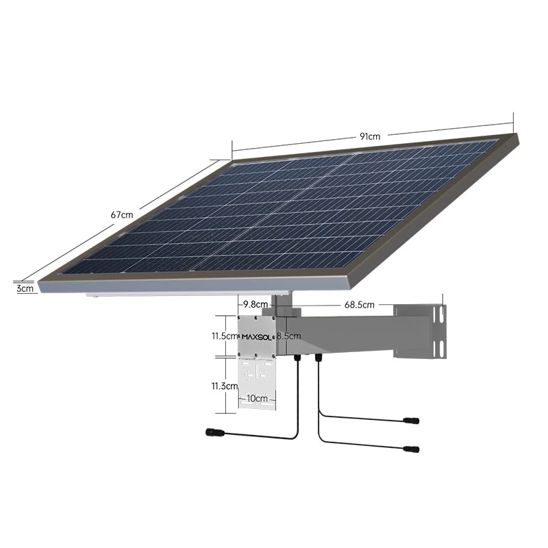
Two Maxsol MPPT-based system examples illustrate why buyers should compare complete configurations rather than controller labels alone. The CS8040 80W and 576Wh solar system documents an 80W monocrystalline panel, 12.8V 45Ah 576Wh LiFePO4 battery, MPPT controller and three DC12V outputs, with optional RS485.
The CS12060 120W and 768Wh solar system documents a 120W monocrystalline panel, 12.8V 60Ah 768Wh LiFePO4 battery, MPPT controller and three DC12V outputs, also with optional RS485.
These are selection examples, not proof of runtime or universal site suitability, and they should not be treated as a tested compatible bundle with unrelated equipment. Verify the current datasheet and supplied configuration, including PV voltage, current and power limits, charging temperatures, protection behaviour and battery settings.
When each controller approach is appropriate
Choose PWM when the system is simple and has ample margin
PWM can be a reasonable choice where all of the following are true:
- The panel and battery voltages are deliberately matched.
- The array-to-controller cable is short.
- The load is small or intermittent.
- There is substantial solar and battery margin.
- Future expansion is unlikely.
- The cost of an occasional energy shortfall is low.
- The controller provides the exact LiFePO4 charging settings required.
A small non-critical device operating seasonally may fit this profile. PWM should not be selected solely because its current rating appears adequate; voltage matching and seasonal performance remain essential.
Choose MPPT when energy recovery and design flexibility matter
MPPT is generally the better fit where:
- The load operates continuously.
- Winter energy margin is tight.
- The panel Vmp is substantially above battery voltage.
- The design uses series-connected panels.
- The panel cable is long.
- The site experiences variable irradiance.
- Expansion or panel substitution may occur.
- Undercharging could trigger costly site visits.
- Monitoring or configurable charge control is required.
Outdoor CCTV, point-to-point wireless links, access points and remote network equipment often justify MPPT because their loads continue overnight and may be operationally important. MPPT does not guarantee uninterrupted service, however. The array, battery, load and environmental design still determine whether the system has enough energy.
Avoid these common selection mistakes
- Comparing controllers only by advertised efficiency.
- Using panel wattage without checking Voc, Vmp, Isc and Imp.
- Calculating series voltage at standard conditions but ignoring cold weather.
- Exceeding the controller’s charge-current limit with an oversized array.
- Assuming the battery BMS will correct an unsuitable charge profile.
- Enabling lead-acid equalisation for LiFePO4.
- Ignoring night-time controller and communications consumption.
- Treating nominal battery Wh as fully usable delivered energy.
- Expecting MPPT to compensate for persistent shading.
- Installing indoor-rated equipment outdoors without suitable protection.
- Omitting cable voltage drop, fusing and conductor-temperature checks.
The practical decision is not simply “MPPT is efficient” or “PWM is cheaper”. Select the controller that keeps the proposed array within its worst-case voltage and current limits, follows the battery’s required charging profile, consumes an acceptable amount of standby power and provides enough seasonal energy margin for the load.
As a next step, compare the linked Maxsol models and their current supplied configurations against your required port count, equipment load, cable distance, power budget, site environment and management needs. Confirm all controller, battery and protection limits before final specification.