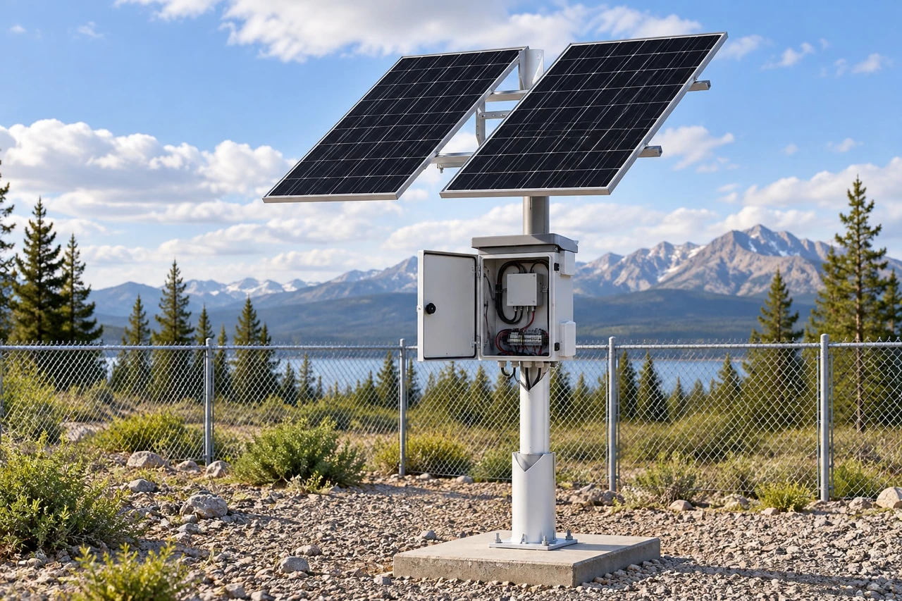
Five Key Factors for an Outdoor Solar Power System
Compare load, winter sun, battery autonomy, installation and expansion before choosing an outdoor solar power system for a New Zealand site.
By Maxsol Team

Choosing an outdoor solar power system starts with five checks: the verified electrical load, solar access during the design month, battery autonomy under expected temperatures, installation and maintenance conditions, and the system’s ability to support future changes. A large panel or battery alone does not confirm that a system will operate reliably.
For New Zealand projects, the most useful supplier comparison is based on evidence rather than headline wattage. Ask each supplier to show how its proposed panel, battery, controller, outputs, mounting arrangement and protection match the same documented site requirements.
1. Verify the load and electrical interfaces
The first factor is the complete load profile—not simply the number of cameras, radios or network devices. Record each device’s normal demand, peak demand, operating schedule, input voltage and connection type before comparing systems.
A practical load schedule should cover:
- Security cameras, including infrared illumination, heaters or other temperature-dependent functions
- Wireless access points, point-to-point bridges and cellular equipment
- Network switches, routers, recorders and control equipment
- Relays, sensors, lighting and cabinet ventilation
- DC converters, Power over Ethernet equipment and other interface devices
- Any intermittent or planned future loads
Use measured power data where possible. A product’s maximum input rating can be useful for checking worst-case demand, but it may not represent normal operation. Conversely, relying only on a low average measurement can overlook startup peaks, night-time infrared operation or periods of heavy wireless traffic.
Check the complete power path
A nominally compatible voltage does not guarantee a compatible system. Confirm:
- Required device voltage and allowable voltage range
- AC or DC input
- Connector type, dimensions and polarity
- Maximum continuous current for each output
- Combined controller or distribution-board output limit
- Cable voltage drop at the proposed distance
- Converter efficiency and idle consumption
- Fuse or circuit-breaker arrangements
- Earthing, surge protection and isolation requirements
This is particularly important for PoE devices. A solar system with DC12V outputs does not necessarily connect directly to a PoE camera or access point. The design may require a DC-powered PoE switch or a suitable converter, and its losses must be included in the load schedule.
For example, the Maxsol CS6030 60W and 384Wh system documents a 60W monocrystalline panel, 12.8V 30Ah 384Wh LiFePO4 battery, MPPT controller and three DC12V outputs. Those specifications provide a starting point for comparison, but they do not establish compatibility with a particular camera, PoE switch or site. The current datasheet, supplied configuration, output limits and all interface requirements still need to be checked.
Evidence to request
Ask a prospective supplier to provide:
- A load schedule showing every powered device
- The assumed normal and peak demand
- Conversion and cable-loss assumptions
- Output voltage, connector and current details
- The controller’s total load limit
- The remaining electrical margin
Avoid proposals based solely on statements such as “supports four cameras”. Camera demand varies significantly by model and operating mode. For a surveillance-specific review, see this guide to choosing a solar power system for outdoor security cameras.
2. Assess design-month solar access and shading
A solar system should be assessed against the site’s difficult solar period, not just annual averages or favourable summer conditions. In many New Zealand installations, shorter winter days and a lower sun angle will be central to the design, but the appropriate design month depends on the location, terrain, weather exposure and required service level.
The supplier should identify the solar resource used in its calculations and explain why it is suitable for the site. A nationwide estimate or an unspecified “sun hours” figure is not enough for a procurement decision.
Inspect the actual solar window
A site survey should consider:
- Hills, ridgelines and cuttings that delay sunrise or bring early shade
- Trees and vegetation at their current and likely future height
- Buildings, poles, towers, antennas and security fences
- Seasonal changes in the sun’s path
- Panel orientation and tilt
- Dirt, salt, bird fouling, leaves, frost or snow where relevant
- Space between rows or modules if multiple panels are used
- Possible shading from equipment mounted on the same pole
Partial shading can reduce energy harvest even when most of a panel appears to be in sunlight. Photographs taken at midday are therefore not sufficient evidence. Request a documented shading assessment covering the expected operating year, especially the design month.
In New Zealand, a north-facing panel commonly offers favourable overall solar exposure, but orientation should follow the actual site assessment. Terrain, available mounting surfaces, morning fog, afternoon shading, wind loading and the required seasonal performance can change the preferred arrangement.
Compare assumptions, not only panel wattage
When reviewing supplier proposals, ask each one to state:
- The location data used for solar estimation
- The selected design month
- Assumed panel orientation and tilt
- Allowance for shading
- Allowance for system losses and panel soiling
- The daily energy expected under the design assumptions
- How the battery will recover after a low-solar period
A larger panel may improve energy recovery, but only if it can be mounted with useful solar access and remains within the controller’s input limits. Panel wattage should therefore be evaluated together with the controller, battery charging requirements and mounting location.
Do not accept a universal runtime or 24/7 operating claim without the assumptions behind it. Continuous operation depends on the load, usable stored energy, solar conditions, control settings, cable losses and temperature.
3. Match battery autonomy, temperature and protection
Battery capacity should be judged by usable energy under defined conditions, not by amp-hours alone. Autonomy is the period for which the system is intended to support the verified load when solar charging is limited or unavailable.
The basic relationship is straightforward: a higher daily load consumes stored energy faster. However, the battery’s nominal watt-hour figure is not automatically the energy available to the equipment. Controller settings, allowable depth of discharge, conversion losses, temperature and protection thresholds all affect usable capacity.
Define the required autonomy
The project team should decide how the system should behave during poor solar conditions. Useful questions include:
- How many low-solar days should the design account for?
- Must every device remain active, or can non-critical loads be reduced?
- Is temporary shutdown acceptable?
- Should the system disconnect loads before damaging the battery?
- How quickly should it recover once solar input returns?
- Is remote low-voltage or battery-status monitoring required?
The answer is operational, not purely technical. A camera protecting a critical access point may need a different design margin from a temporary monitoring device where occasional downtime is acceptable.
If the project requires a detailed energy calculation, use a structured method for sizing an off-grid solar power system for CCTV. For supplier selection, the priority is to ensure every bidder uses the same load, autonomy target and design-month assumptions.
Temperature matters on both charge and discharge
Battery performance and permitted charging conditions can change with temperature. This matters for equipment installed in exposed cabinets, elevated locations or areas with cold winter nights and strong daytime sun.
Confirm:
- The battery’s permitted charging and discharging temperature ranges
- Whether charging protection is provided at temperature limits
- Where the temperature sensor is located
- Whether the enclosure can experience solar heat gain
- Controller low-voltage disconnect and reconnect settings
- Overcurrent, short-circuit and reverse-polarity protection
- Whether the battery management and controller settings are matched
Do not assume that LiFePO4 chemistry removes the need for temperature management. The battery, controller, enclosure and site environment must be assessed as one system.
As a mid-scale reference, the Maxsol CS12060 120W and 768Wh system documents a 120W monocrystalline panel, 12.8V 60Ah 768Wh LiFePO4 battery, MPPT controller and three DC12V outputs. These are nominal specifications, not a guaranteed autonomy period. Runtime depends on the connected load and installation conditions, while charging temperatures, controller limits and protection should be confirmed from the current documentation.
4. Plan outdoor mounting, cabling and maintenance
An electrically adequate system can still underperform if the panel is shaded, cables are undersized, connectors admit moisture or maintenance access is impractical. Outdoor installation quality is therefore a core selection factor rather than an afterthought.
The proposed layout should show where the panel, battery, controller, network equipment, antennas and protective devices will be mounted. It should also identify cable routes and separation between power, data and earthing conductors.
Evaluate the mounting location
Check whether the mounting design addresses:
- Wind exposure and the structural load of panels and brackets
- Panel tilt and resistance to unwanted movement
- Pole or wall strength
- Safe installation and maintenance access
- Tampering, theft and accidental impact
- Vegetation growth and future shading
- Water drainage and condensation
- Coastal salt, dust, agricultural contaminants or other local exposure
- Heat generated by electronics inside the enclosure
A supplier should identify which mounting components are included and which must be designed or sourced separately. Do not infer environmental suitability from a product photograph or cabinet appearance. Request the relevant specifications for the supplied components.
Review every cable run
Long DC cable runs can create enough voltage drop to affect equipment operation, particularly when current rises or battery voltage is near the controller’s disconnect threshold. The proposal should state conductor size, route length, current assumptions and acceptable voltage drop.
Also confirm:
- Outdoor suitability of exposed cable and conduit
- Connector sealing and strain relief
- Drip loops and cable-entry direction
- Protection against abrasion and sharp edges
- Separation or coordination of power and data cabling
- Surge-protection location and earthing method
- Labelling of circuits, polarity, fuses and disconnects
- Service loops and access for testing
For wireless installations, panel placement must not interfere with antenna alignment or the required radio path. Likewise, an enclosure should not be positioned where it blocks an antenna or makes future realignment unsafe.
Make maintenance requirements explicit
Every off-grid installation needs inspection. The frequency will depend on the environment and project requirements, so it should be agreed rather than assumed.
A useful maintenance plan identifies how technicians will:
- Clean and inspect the panels
- Check for new shading
- Inspect brackets, fasteners and cable supports
- Examine connectors and cable entries
- Review controller or battery alarms
- Test output voltage under load
- Confirm protective devices remain correctly rated
- Update the load record after equipment changes
Ask whether common service tasks require specialist tools, removal of major components or work at height. Maintenance cost and accessibility can distinguish two systems that look equivalent on a specification sheet.
5. Consider lifecycle support and expansion
The final factor is whether the system can be maintained, documented and expanded over its operating life. Spare output capacity is useful only when the controller, battery, panel array, cabling and protection can all support the added load.
Projects often change after commissioning. A second radio may be added, a fixed camera may be replaced with a higher-demand model, or remote monitoring may be introduced. Each change alters the energy balance.
Ask what can genuinely be expanded
Before selecting a platform, confirm:
- Available output count and output type
- Per-output and combined current limits
- Controller solar-input limits
- Permitted panel configurations
- Battery configuration and replacement requirements
- Space for additional network or protection equipment
- Whether larger cables or protective devices would be needed
- Availability of configuration records and wiring diagrams
- How replacement components are identified
- Whether monitoring or management interfaces are required
Do not assume that another panel or battery can simply be connected later. The controller may have voltage, current or charging constraints, while parallel batteries may require matching and configuration rules. Any proposed expansion should be checked against current manufacturer documentation.
Maxsol’s documented systems illustrate how headline scale can vary:
| Scale example | Documented panel configuration | Documented battery | Controller and outputs | What the buyer must still establish |
|---|---|---|---|---|
| CS6030 solar power system | 60W monocrystalline panel | 12.8V 30Ah, 384Wh LiFePO4 | MPPT; three DC12V outputs | Actual load compatibility, usable autonomy, environmental suitability and interfaces |
| CS12060 solar power system | 120W monocrystalline panel | 12.8V 60Ah, 768Wh LiFePO4 | MPPT; three DC12V outputs | Design-month generation, charging conditions, controller limits and mounting requirements |
| CS400150 solar power system | Two 200W modules, 400W total | 12.8V 150Ah, 1920Wh LiFePO4 | MPPT; four DC12V outputs | Site-specific runtime, cable design, supplied configuration, protection and expansion limits |
These products are scale examples rather than guaranteed matches for an unspecified site. Moving to a higher panel and battery rating may provide more energy capacity, but it does not resolve an incompatible voltage, excessive cable loss, poor winter solar access or unsuitable installation arrangement.
Compare documentation and support
Lifecycle support is easier when the supplier can provide clear, version-controlled information. Request:
- Current product datasheets
- Wiring and connection diagrams
- Controller settings and limits
- Battery charging and temperature requirements
- Installation and maintenance instructions
- Parts identification
- Fault indicators and diagnostic procedures
- A record of exactly what is included in the quoted configuration
Maxsol is a solution-oriented outdoor power and networking brand founded in 2019, with a portfolio that includes LiFePO4 solar systems, outdoor enclosures, networking equipment and power accessories. Regardless of brand, procurement should remain based on the documentation for the specific configuration being offered.
Five-factor supplier comparison checklist
Use the same checklist for every proposal so differences remain visible.
| Comparison area | Questions to ask | Evidence to request | Common warning sign |
|---|---|---|---|
| Verified load and interfaces | Are all devices, peaks, operating modes and conversion losses included? | Device schedule, measured or documented loads, output and connector details | Selection based only on device count |
| Design-month solar access | Which month, location, orientation and shading assumptions were used? | Solar assumptions, site layout and shading assessment | Annual average or unspecified “sun hours” |
| Battery autonomy and temperature | What autonomy is targeted, and under what load and temperature conditions? | Energy balance, controller settings and battery operating limits | Runtime claim without stated assumptions |
| Outdoor installation and maintenance | How will panels, enclosure, cables, protection and earthing be installed and serviced? | Layout, cable schedule, mounting details and maintenance plan | No allowance for voltage drop, access or environmental exposure |
| Lifecycle support and expansion | What can be added or replaced without exceeding system limits? | Datasheets, wiring diagrams, controller limits and configuration records | Expansion promised without electrical checks |
Before approval, write the chosen assumptions into the project documentation. At minimum, record the design load, design month, autonomy target, panel position, battery and controller settings, cable lengths, output allocation and maintenance responsibilities. This gives installers and future technicians a clear baseline for testing and changes.
As a practical next step, compare the linked Maxsol models against the project’s required port count, measured load, cable and wireless distance, power interfaces, outdoor environment and management requirements. Then verify the current datasheet and supplied configuration before treating any model as a suitable match.